Conversion Of Pictorial Views Into Orthographic Views
*Whag are pictorial views?
-A view of an object (actual or imagined) as it would be seen by an observer who looks at the object either in a chosen direction or from a selected point of view. Pictorial sketches often are more readily made and more clearly understood than are front, top, and side views of an object.
* Basic Types of pictorial views .
There are three basic types of pictorial drawings: axonometric, oblique, and perspective. ... Figure 1 also shows a front view in each case for comparison, and brings out the fact the axonometric projection is a special case of orthographic projection.
A Pictorial drawing provides a 3D image to help understand the shape of an object or to assist in interpreting a drawing. There are 3 main ways to draw a pictorial drawing,
1. Isometric, 2. Oblique, 3. Perspective.
(Other methods of Pictorial drawings include dimetric drawing, trimetric drawing)
1. Isometric drawing
Definition – An Isometric drawing is a pictorial representation of an object in which all three dimensions are drawn at full scale. The term isometric means “equal measurement”.
Pictorial Drawing isometric
Isometric steps
Isometric drawing is the most commonly used method of pictorial drawing. Isometric drawings are built on three lines, called isometric axes. One is drawn vertically and the other two with the 30° set square either side of it. An Isometric drawing is a way of presenting designs in three dimensions (3D). They can be completed using the 30/60 set square or freehand. An Isometric drawing is one of a family of three-dimensional views called pictorial drawings. In an isometric drawing, the object’s vertical lines are drawn vertically, and the horizontal lines in the width and depth planes are shown at 30 degrees to the horizontal. The true dimension of the object is used to construct the drawing. These dimension can be taken from either drawings completed in orthographic or by measuring an object. Isometric drawings or images have become the industry standard for parts manuals, technical proposals, patent illustrations and maintenance publications due to their use of true length and the ability for untrained people to understand. An isometric projection results if the plane is oriented so that it makes equal angles with the three principal planes of the object. The representation of the object seen below is an isometric drawing of a cube.
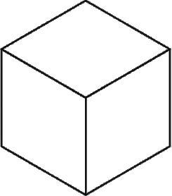
Isometric Cube
Isometric Cube
In this drawing the three visible faces appear as equilateral parallelograms; that is, while all of the parallel edges of the cube are projected as parallel lines, the horizontal edges are drawn at an angle (usually 30°) from the normal horizontal axes, and the vertical edges, which are parallel to the principal axes, appear in their true proportions.
2. Oblique projection
Oblique projection is probably the simplest method of producing a pictorial drawing because surfaces are directly in front of the viewer will look very similar to the front view in an orthogonal drawing. It is a method of drawing objects in 3 dimensions and may be drawn at any angle although 45⁰ is generally used. It is quite a simple technique compared to isometric or even perspective drawing. However, to draw accurately in oblique projection traditional drawing equipment is needed. Oblique projections illustrate the general 3 dimensional shape of the object. However only faces of the object parallel to the plane of projection are shown at there true size and shape. In fact, the oblique projection of these faces is the same as an orthographic front view.
Cavalier and Cabinet Projection
Cavalier and Cabinet pictorial drawings of a cube
Diagram 1.1 (a) Cavalier (b) CabinetThere are two specific forms of Oblique drawings. (Diagram 1.1) These are Cavalier and Cabinet projection. The difference between the two is how the depth of the object is represented. A cavalier projection is obtained when the angle between oblique projectors and the plane of projection is 45⁰ and the rear projections are true to size. The resulting figure appears too thick and distorted. A cabinet projection is used to correct this deficiency. Cabinet projection is an oblique projection where the length of the lines projecting backwards are halved. Diagram 1.1 shows a drawing of a cube. Diagram (a) has been drawn in Cavalier and diagram (b) is in Cabinet.


👍👍
ReplyDelete